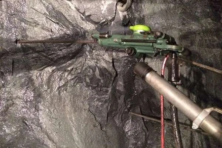
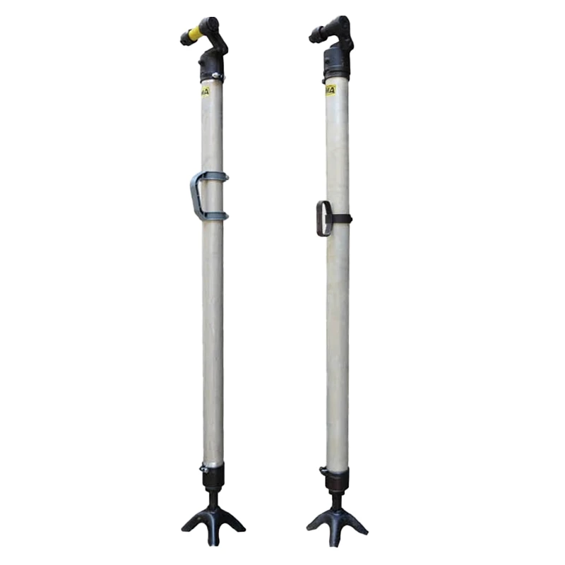
Our full-series rock drill spare parts are OEM-quality replacement components, specially engineered for YT series air-Our FT series rock drill air legs are professional supporting components for pneumatic air-leg rock drills, including mainstream models FT160BC, FT160A, FT140B, FT80 and FT100.
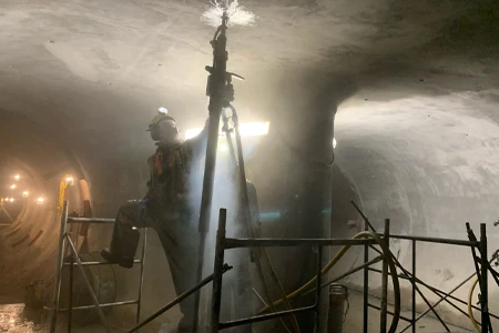
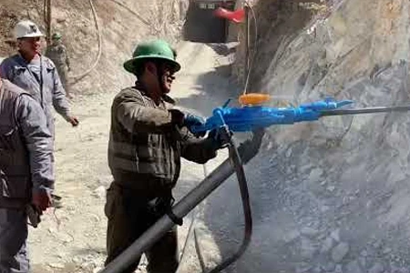
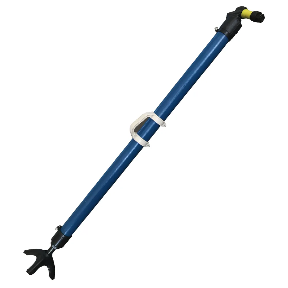
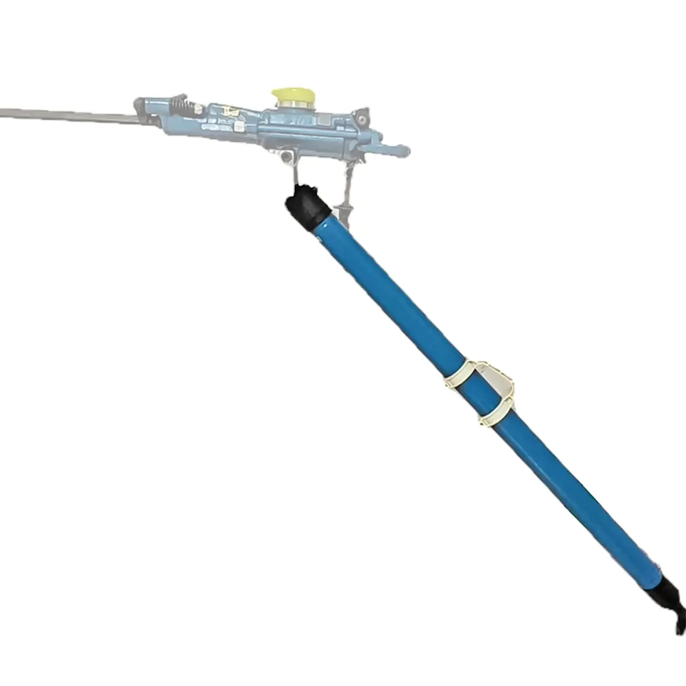
Designed to provide stable reaction force and auxiliary propulsion for rock drilling operations, they effectively reduce operator fatigue and improve drilling efficiency and hole forming accuracy. Made of thickened high-strength aluminum alloy tube with high-performance sealing system, they feature strong bearing capacity, stable telescopic performance, air leakage prevention and long service life.
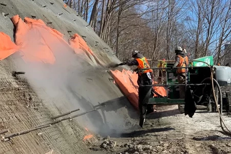
Fully compatible with YT28, YT27, YT24, YT23, YO18, Y20LY and other mainstream pneumatic rock drills, they are standard supporting equipment for mining, tunneling, quarrying and slope stabilization projects worldwide.